LOCATION OF THE LOADING DOCKS
Locate the loading docks to minimize forklift traffic inside the building. Rather than transporting individual pallets inside the building, unload trucks at multiple docks.
Shipping docks and receiving docks can be combined, with shipping and receiving together (Figure 1), or they can be separated, with shipping and receiving in different areas of the building (Figure 2).

Figure 1

Figure 2
Choose the loading dock location based on the needs of the in-plant process. A combined dock works well in smaller buildings where shipping and receiving is infrequent. However, this design may increase in-plant traffic and travel distance.
A separated dock works well in buildings where the materials enter production in one part of the building and the production is completed elsewhere. This design minimizes transportation of materials inside the building.
PLAN ON-SITE TRAFFIC PATTERNS
Design the traffic patterns around the building so that the truck driver is on the inside of each turn, for best control of the truck. Where traffic is on the right side of the road and the driver’s seat is on the left side of the cab, truck movement around the building should be counterclockwise (Figure 3).
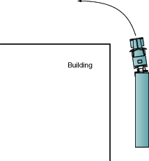
Figure 3
For efficient truck traffic, plan for the following:
- An entrance driveway that accommodates the turning radius of the longest truck expected and allows trucks to be driven forward onto the site, rather than backed up
- Right-angle turns onto the site that have a minimum inside radius of 26 ft and a minimum outside radius of 50 ft (Figure 4)
- One-way access roads that are 13 ft wide minimum (Figure 4)
- Two-way access roads that are 26 ft wide minimum (Figure 4)

Figure 4
- Separate roads for employee traffic
- Truck waiting areas near the loading docks to accommodate all waiting trucks
DESIGN THE APRON SPACE
Apron space is the space between the loading platform and the nearest obstruction. Apron space includes the parking area where the truck parks at the dock and the maneuvering area, which is the area the truck uses to maneuver in and out of the parking area (Figure 5) and (Figure 6). The recommended center distance between dock positions is 12 ft minimum.

Figure 5

Figure 6
The minimum apron space required depends on the:
- Center line distances between the parked trucks at the dock
- Length of the trucks
- Steering geometry of the trucks
Less apron space is needed if the trailers will be parked with the tractors detached.
The minimum apron space for a typical 40 ft container rig is listed in Table 1.

Table 1
If expected trucks are longer than 40 ft, increase the apron space proportionately. For example, if the dock can accommodate 48 ft trailers, increase the apron space in the table by 20%. If the traffic pattern causes the driver to be on the outside of a turn, add 50 ft.
Always provide a concrete landing gear pad to support the trailer’s landing gear when the trailer is detached (Figure 7). The landing gear is about 33 ft from the back of the trailer on a standard 40 ft container chassis. The gear is about 11 ft from the back of the trailer on a 20 ft chassis. The pad should be wide enough to accommodate all expected types of trailers. It is helpful for the pad to extend all the way back to the loading platform. The pad should be designed to support two point loads of 25,000 lb each, 6 ft apart, to support a fully loaded trailer.

Figure 7
DOCK APPROACH
The maximum grade percentage from the loading dock to the vehicle is determined by the height of the dock (discussed in detail in Set the Dock Height on page 10). When using electric powered loading equipment, the maximum grade percentage is 10%. For gas or diesel powered loading equipment the maximum grade percentage is 15%. If these grade percentages are exceeded, damage to handling equipment and load spillage may result.
If the plant floor is at grade, or has a low grade, recess the truck parking area so that the trailer bed will be at about the same height as the plant floor (Figure 8). The parking area will slope down toward the dock. The slope should be 6% or less. If heavy loads are expected, the slope should not exceed 5%. If necessary, slope may be increased to an absolute maximum of 10%, and only for light loads. Steep slopes may cause loads to topple.
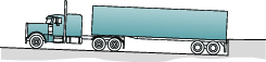
Figure 8
Always provide drainage for recessed parking areas. The area next to the building should slope slightly away from the building for a short distance of 1 to 3 ft (Figure 9). A short distance is preferable so that the position of the trailer’s rear axle will have less of an effect on the height of the trailer bed at the dock.
Figure 9
Drawbacks of a declined dock approach include the following:
- Difficult removal of snow
- Drainage of water
- Debris buildup
- High impact forces to the building wall and dock
When a declined dock approach is used, give special attention to other loading equipment. Dock seals must be tapered to match the angle of the trailer. If the seals are not tapered, sealing will not be effective and the seal may be damaged. Truck restraints must also be projected sufficiently to ensure proper operation and safety.
Preventing dock approach impact is easily done. For new constructions, project the dock sufficiently to prevent the top of the trailer from impacting the building wall. When reconstructing an existing facility where it is not possible to project the dock, project the bumpers by using bumper block outs.

Figure 10

Figure 11
The required projection is calculated based on the grade percentage. To calculate the grade, determine the difference in height between the dock and a fixed point approximately 50 ft directly out from the dock. Grade equals the height difference divided by the length measured.
Example:
22 in. difference over 600 in. distance
22 ÷ 600 = 0.03
0.03 x 100 = 3% grade
For proper dock operation, declined dock approaches should be no more than 10%
Use Table 2 to determine the proper projection.
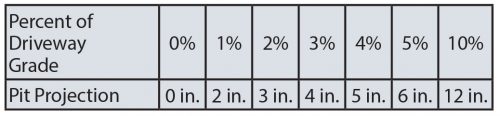
Table 2
SELECT THE LOADING DOCK CONFIGURATION
Important factors in dock configuration include:
- Security
- Traffic control
- Safety
- Worker comfort
- Space availability
- Climate
The two main types of dock configurations are the inside/outside dock and the open dock.
Inside/Outside Dock
In an inside/outside dock configuration, the loading platform is inside the building (Figure 12). With the proper door sealing system, an inside/outside dock provides excellent weather protection and security. The refrigerated dock is a common version of the inside/outside dock.

Figure 12
The inside/outside dock design may require the building wall to be set back from the edge of the dock (Figure 13), especially for docks with recessed parking areas. The setback works to:
- Protect the building wall from impact damage
- Protect projections, such as overhangs or signs
- Facilitate the installation of sealing systems
- Minimize injury hazards
Clearance is required between the truck and the building wall. Allow for at least 6 in. of clearance between the rear of the truck and the building wall, measured at 6 ft above the dock platform. Allow a 4 in. minimum clearance between the top of the trailer and the building wall (Figure 13).

Figure 13
Refrigerated docks require a vestibule between the platform and refrigerated area. The vestibule creates an air lock between the outside and the refrigerated area (Figure 14), which will minimize the inflow of warm air. A carefully designed refrigerated dock will greatly reduce energy usage.

Figure 14
Open Dock
In an open dock configuration, the loading platform is outside the building (Figure 15). Open docks are common in temperate climates. Adding a canopy over the loading platform and curtains around the dock perimeter (Figure 16) will provide some protection. When placing canopies over docks on sloped approaches, the height of the canopy must accommodate the height of the sloped truck.

Figure 15

Figure 16
An open dock requires sufficient maneuvering space for forklifts between building wall and the dock levelers. Safety barriers such as concrete posts or chains are necessary to reduce the risk of forklifts driving off the dock (Figure 17).

Figure 17
Additional Dock Configurations
Building and property limitations may require other types of loading docks.
Saw-Tooth Dock
A saw-tooth design requires less apron space than an inside/outside or open dock (Figure 18).

Figure 18
Table 3 shows the required amount of apron space as dependent on center distance and saw tooth angle. The table is based on a 53 ft trailer with the tractor attached during loading.
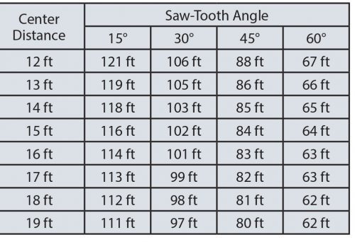
Table 3
If smaller trucks will use the dock, decrease apron space proportionately. If tractors will be detached from the trailers, decrease the required apron space shown in the table by 24 ft, 22 ft, 18 ft, and 14 ft for 15°, 30º, 45°, and 60° angles respectively.
Example: If the center distance between the dock positions is 17 ft and the saw tooth angle is 30°, the required apron space is 99 ft minus 22 ft, or 77 ft.
Pier Dock
If dock positions cannot be placed along the building perimeter, a loading dock pier can be used (Figure 19).

Figure 19
Self-Standing Dock
If space inside the building does not permit a loading platform, a self-standing dock structure can be added outside the building (Figure 20).

Figure 20
Flush Dock
The face of a flush dock is flush with the buildings outside wall. To prevent wall damage and protect dock seals on a level approach, project the foundation or bumper 4 in. beyond the outside wall. If the building wall extends beyond the face of the dock, add additional foundation or bumper projection.
Enclosed Dock
Use an enclosed dock when climate control, freight protection, security, and overhead lift are required. Enclosed docks involve high construction expenses and consideration of vehicle exhaust pollution.
Depressed Dock
Use a depressed dock with a sloped approach where the facility construction does not allow basements and floors at the dock level. Plan the driveway grade cautiously. To avoid the top of the truck hitting the building wall, cargo toppling, or pull-away traction problems resulting from ice or snow, do not allow the grade to exceed 10%.
DETERMINE THE NUMBER OF DOCK POSITIONS
To determine the required number of dock positions, obtain:
- Number of trucks to be served
- Average time to load or unload each truck
- Timing of each truck arrival and departure
Consider peak periods of use when determining the number of dock positions. Peak periods of use can be daily, weekly, monthly, seasonally or yearly.
NOTE: Consider providing one dock position for trash collection.
Use the following formula to determine the number of required dock positions. For the example, we will use 36 trucks served in an 8-hour period (4.5 trucks per hour) with an average turnaround time of 45 minutes (0.75 hours) per truck. Turnaround time includes parking, loading and leaving.
Number of Trucks Per Hour x Turnaround Time Per Truck = Number of Dock Positions
4.5 Trucks Per Hour x 0.75 Hours = 3.375 Dock Positions
In the example, 3.375 dock positions were calculated; therefore, 4 dock positions are required.
If all the trucks arrive within a peak period of 4 hours, 6.75, or 7, dock positions would be required.
NOTE: If the number of required dock positions cannot be provided, consider providing a truck waiting area.